Module 3: Routing and Physical Optimization
Prerequisites
Before proceeding, ensure your Module 2 CTS run (classic_to_cts) has completed
successfully. This module resumes the flow from the Post-CTS STA checkpoint
using --with-initial-state, so no design work needs to be repeated.
Table of Contents
1. Global Routing (GRT)
1.1 What Global Routing Does
Global Routing is the first stage of the routing process.
Given a detailed placed ODB design, the router assigns coarse routing regions
for each net so they can later be connected with real metal wires.
At this stage, no physical wires are created yet. The router only generates a high-level routing plan that helps guide the next routing step.
Global routing also allows the tool to compute more accurate estimates of wire resistance and capacitance, which improves the timing analysis results.
1.2 GRT Configuration Reference
The following parameters govern the behaviour of the Global Router (OpenROAD.GlobalRouting).
All values listed are the defaults used in this workshop run unless explicitly overridden
in Section 6.
Parameter |
Type |
Description |
Default |
|---|---|---|---|
|
|
Reduction in the routing capacity of the edges between the cells in the global routing graph for all layers. Values range from 0 to 1. 1 = most reduction, 0 = least reduction. |
|
|
|
If |
|
|
|
Maximum iterations the global router will attempt to resolve routing overflow before stopping. |
|
|
|
The highest metal layer available for signal routing. |
|
|
|
The lowest metal layer available for signal routing. |
|
2. Post-GRT Design Repair
After Global Routing assigns approximate wire paths, routing-aware RC estimates
become available. LibreLane can optionally run a design repair pass
(OpenROAD.RepairDesignPostGRT) to address violations that appear once these
routing estimates are considered.
This step performs similar optimizations to the post-CTS repair from Module 2, such as buffer insertion and gate resizing. However, it now uses routing-aware parasitic estimates from Global Routing instead of purely placement-based estimates, allowing more targeted timing fixes.
Key repair parameter:
Parameter |
Type |
Description |
Default |
|---|---|---|---|
|
|
Enables resizer timing optimizations after global routing using the |
|
|
|
Enables the |
|
|
|
Maximum wire length in µm that the post-GRT Resizer will allow before inserting a repeater buffer. |
|
|
|
Enables running GRT before and after running resizer |
|
|
|
Specifies a margin for the slews during post-grt design repair. |
|
|
|
Specifies a margin for the capacitances during design post-grt repair. |
|
|
|
Used to guide timing optimization after global routing. It instructs the optimizer not to stop at zero setup slack and try to achieve a positive setup slack (the specified margin). |
|
|
|
Specifies a time margin for the slack when fixing hold violations. Normally the resizer will stop when it reaches zero slack. This option allows you to overfix. |
|
|
|
Specifies a max number of buffers to insert to fix hold violations. This number is calculated as a percentage of the number of instances in the design. |
|
|
|
Specifies a max number of buffers to insert to fix setup violations. This number is calculated as a percentage of the number of instances in the design. |
|
|
|
Allow setup violations while fixing hold violations after global routing. |
|
3. Antenna Verification
3.1 What is an Antenna Violation?
During chip fabrication, wafers pass through a plasma etching process to pattern each metal layer. As metal is etched, floating conductor segments accumulate a static charge proportional to their exposed area. If this charge exceeds a threshold, it can tunnel through the thin gate oxide of connected transistors — permanently damaging them.
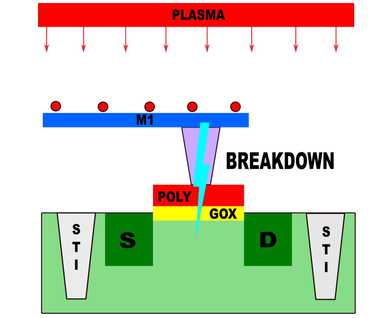
Fig. 18 Antenna Effect
This is the Antenna Effect (formally: Process Antenna Rule violation). The ratio that governs it is:
Antenna Ratio = Total metal area connected to gate / Gate oxide area
The SkyWater 130nm PDK defines maximum allowable ratios for each metal layer and via. When a net’s accumulated metal area exceeds these limits, the router must intervene.
Why Does This Appear After Global Routing?
Antenna violations are a function of physical wire length and shape — information that
only becomes available once Global Routing assigns nets to metal layer paths. The check
is performed immediately after GRT using the OpenROAD.CheckAntennas step.
3.2 Antenna Repair Strategies
LibreLane provides two complementary repair mechanisms, which can be used individually or together:
Antenna Diode Insertion
Insert specialised diode cells connected to the violating net. The diode provides a controlled discharge path to the substrate during fabrication, protecting the gate oxide. This is the primary repair method for most violations.
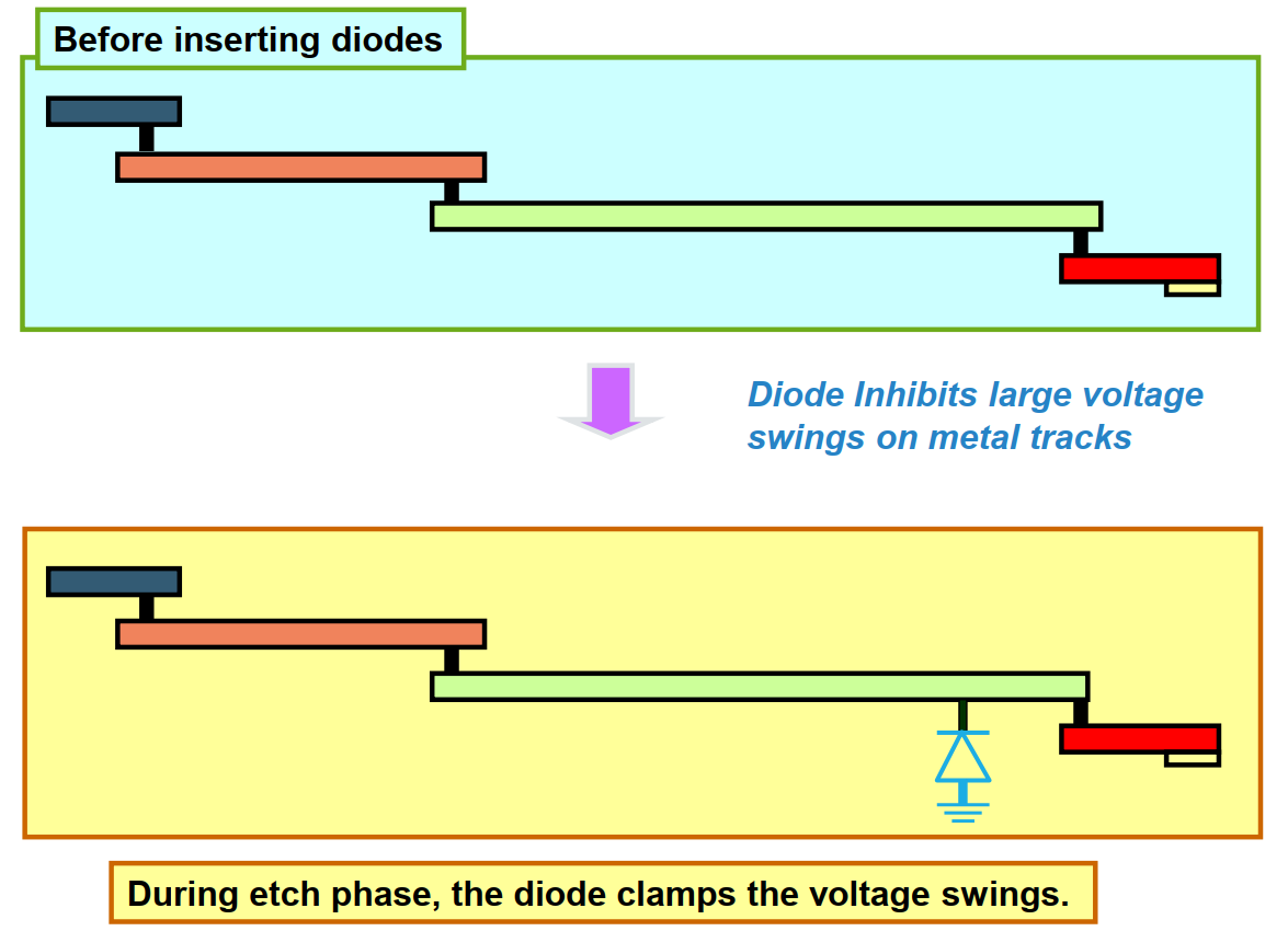
Fig. 19 Solution 1 Inserting Diodes
Metal Jumpering (Layer Hopping)
Break a long continuous metal segment into shorter sections by routing through a higher metal layer and back down. This resets the accumulated charge at the via, allowing the net to continue without exceeding the ratio limit.
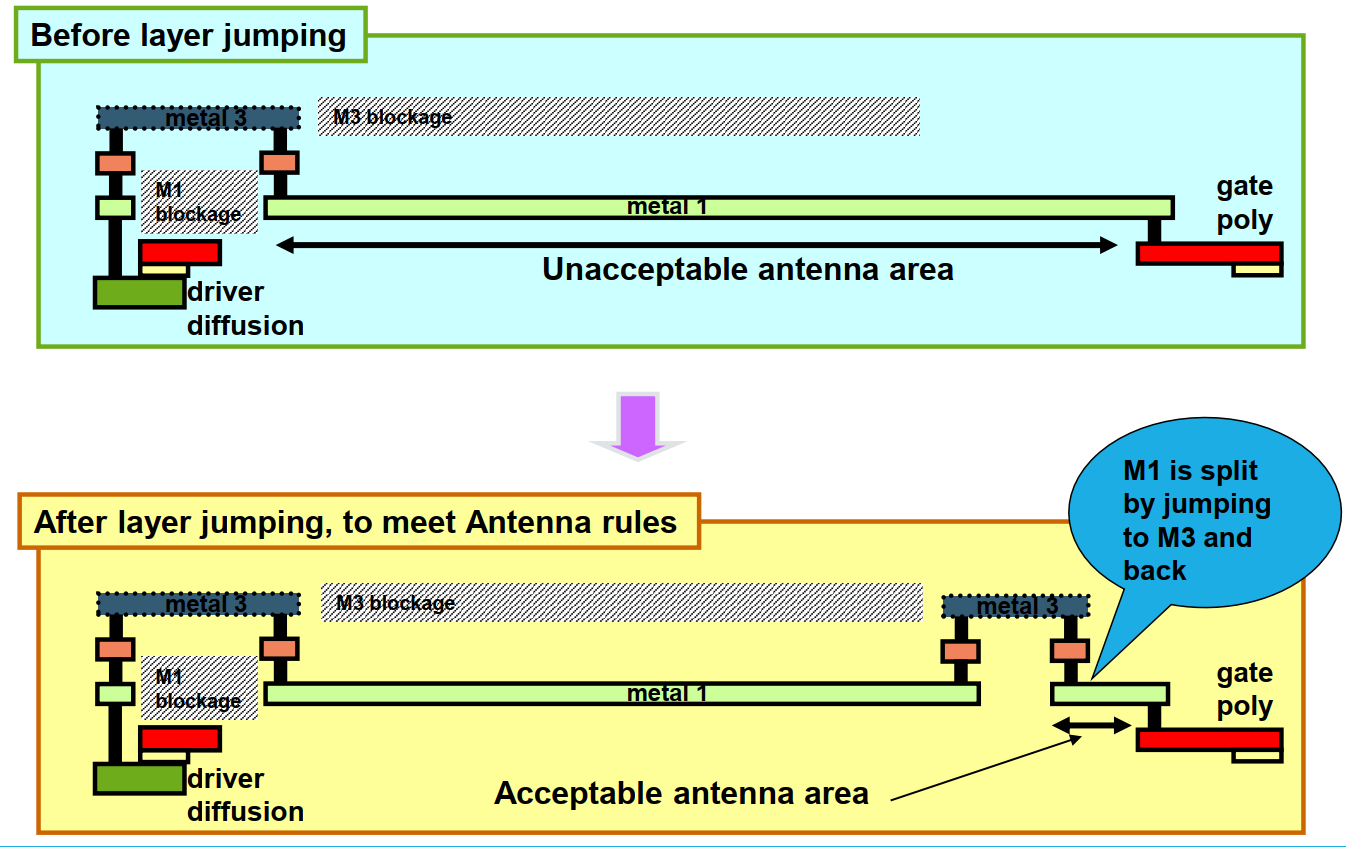
Fig. 20 Solution2 Layer Jumping
The repair process is iterative: after each repair pass, the antenna checker re-evaluates the design. Iterations continue until all violations are resolved or the configured iteration limit is reached.
Tip
For the aes_wb_wrapper, diode insertion is often more effective because the
AES datapath contains several wide bus signals (such as wbs_dat_o and key
register buses). These buses can accumulate large metal areas on lower routing
layers, increasing the risk of antenna violations.
Jumper insertion is typically more effective for isolated long nets, but it is less efficient when many parallel bus wires are involved.
3.3 Antenna Repair Configuration
Parameter |
Type |
Description |
Default |
|---|---|---|---|
|
|
Maximum repair iterations for global antenna violations. |
|
|
|
Percentage margin above the PDK limit used to over-fix violations. A value of |
|
|
|
Restricts repair to metal jumpering only. Cannot be combined with |
|
|
|
Restricts repair to diode insertion only. |
|
|
|
Maximum antenna repair iterations during Detailed Routing. |
|
|
|
Margin percentage for over-fixing violations during Detailed Routing. |
|
|
|
Enables the |
|
|
|
A Manhattan distance above which a diode is recommended to be inserted by the heuristic inserter. |
|
|
|
Unconditionally inserts diodes on design ports diodes on ports, to mitigate the antenna effect. |
|
4. Detailed Routing (DRT)
4.1 What Detailed Routing Does
Detailed Routing is the most computationally intensive step in the entire flow. It transforms the abstract G-cell routing plan from Global Routing into actual metal wires and vias that strictly satisfy all SkyWater 130nm DRC rules — minimum spacing, minimum width, via enclosure, and antenna ratios.
The engine used by LibreLane is TritonRoute, which operates in multiple passes:
Pass |
Description |
|---|---|
Track assignment |
Assigns each global route to a specific routing track on the target metal layer. |
Detailed path search |
Performs local rerouting to resolve shorts, spacing violations, and via conflicts. |
Iterative optimisation |
Repeats the search-and-repair cycle for up to |
Post-DRT legalisation |
Updates the design database with final wire geometries and newly inserted antenna cells. |
Note
A successful Detailed Routing run ends with 0 DRC violations. If violations remain after the maximum iteration count, they will appear in the post-DRT DRC report and must be resolved before the design can proceed to Physical Signoff.
4.2 DRT Configuration Reference
Parameter |
Type |
Description |
Default |
|---|---|---|---|
|
|
Number of CPU threads used by TritonRoute. If unset, defaults to the machine’s available thread count. Increase this on multi-core workstations to reduce run time. |
|
|
|
Maximum optimisation iterations TritonRoute will attempt to achieve 0 DRC violations. |
|
|
|
Saves an |
|
|
|
Write a DRC report every N iterations. Defaults to |
|
|
|
Specify non-default rules. Can be used to change the width, spacing and vias of a net. |
|
|
|
Specify which nets should be assigned to which non-default rule. The net name is a regular expression. Use ‘^name$’ to match an exact name. |
|
6. Configuration Summary and Execution
6.1 Key Parameters for This Run
Three parameters are added or modified relative to the Module 2 configuration:
Parameter |
Value |
Rationale |
|---|---|---|
|
|
Prevents signal routes from being placed on Metal 5. Since the Caravel User Project Wrapper uses |
|
|
Increases the repair over-fix margin from the default 10% to 15%, proactively protecting nets that are close to the antenna limit from violations introduced during Detailed Routing. |
|
|
Enables the post-GRT design repair step, allowing the Resizer to fix violations using real RC parasitics from Global Routing. |
Why met4 as the Maximum Routing Layer?
The SkyWater 130nm metal stack for the sky130_fd_sc_hd library has five signal
routing layers (met1 through met5). In a standalone macro, all five layers are
available. However, when the aes_wb_wrapper is integrated into the Caravel User
Project Wrapper, the wrapper’s PDN uses met5 for horizontal power straps.
Setting RT_MAX_LAYER: "met4" ensures that no signal wire from the macro occupies
met5 tracks, leaving that layer exclusively available for top-level power delivery.
Without this constraint, the Detailed Router may place signal wires on met5 that
collide with the wrapper’s power straps — creating DRC violations that are
difficult to resolve post-integration.
6.2 Final config.json
Open your configuration file and apply all additions:
$ gedit ~/Silicon-Sprint-AUC/openlane/aes_wb_wrapper/config.json
Your complete config.json should now read:
{
   "DESIGN_NAME": "aes_wb_wrapper",
    "PDN_MULTILAYER": false,
    "CLOCK_PORT": "wb_clk_i",
    "CLOCK_PERIOD": 25,
    "VERILOG_FILES": [
        "dir::../../../secworks_aes/src/rtl/*.v",
        "dir::../../verilog/rtl/aes_wb_wrapper.v"
    ],
    "FP_CORE_UTIL": 40,
    "RT_MAX_LAYER": "met4",
    "SYNTH_STRATEGY": "DELAY 4",
    "DEFAULT_CORNER": "max_ss_100C_1v60",
    "RUN_POST_GRT_DESIGN_REPAIR": true,
    "PNR_SDC_FILE": "dir::pnr.sdc",
    "SIGNOFF_SDC_FILE": "dir::signoff.sdc",
    "IO_PIN_ORDER_CFG": "dir::pin_order.cfg",
    "DESIGN_REPAIR_MAX_SLEW_PCT": 30,
    "DESIGN_REPAIR_MAX_CAP_PCT": 30,

    "GRT_ANTENNA_REPAIR_ITERS": 10,
    "GRT_ANTENNA_REPAIR_MARGIN": 15,
     "DIODE_ON_PORTS": "both"
}
6.3 Flow Execution
This run resumes from the Module 2 CTS checkpoint using --with-initial-state.
This avoids re-running the entire synthesis, floorplan, and CTS pipeline, saving
significant compute time.
Ensure you are inside the Nix shell:
$ nix-shell --pure ~/librelane/shell.nix
Then execute:
[nix-shell:~]$ librelane \
    ~/Silicon-Sprint-AUC/openlane/aes_wb_wrapper/config.json \
    --run-tag classic_flow \
    --from OpenROAD.GlobalRouting\
    --to Checker.WireLength \
    --with-initial-state \
    ~/Silicon-Sprint-AUC/openlane/aes_wb_wrapper/runs/classic_flow/38-openroad-stamidpnr-2/state_out.json
Tip
The --with-initial-state flag loads the complete design state (placement, clock tree,
timing data) from the specified state_out.json. LibreLane will begin execution from
the first step that follows the state’s last completed step — in this case, directly
at Global Routing. No design data is lost between modules.
The run will execute through the following key steps before stopping at STAMidPNR-3:
runs/classic_to_drt/
    ├── 39-openroad-globalrouting/           ← GRT + congestion resolution
    ├── 40-openroad-checkantennas/           ← Initial antenna violation scan
    ├── 41-openroad-repairantennas/          ← Diode insertion / jumpering
    ├── 42-openroad-resizertiminpostgrt/     ← Post-GRT timing repair (if enabled)
    ├── 43-openroad-detailedrouting/         ← TritonRoute DRT
    ├── 44-openroad-checkantennas-1/         ← Final antenna check post-DRT
    ├── 45-openroad-stamidpnr-3/             ← STA with routed RC parasitics
    ⋮
Warning
Detailed Routing (43-openroad-detailedrouting) is the most time-consuming step in
the entire flow. For the aes_wb_wrapper, expect a runtime of 30–90 minutes
depending on your machine’s CPU thread count. Do not interrupt this step — an
incomplete DRT database cannot be resumed and the step must be restarted from the
beginning.
7. Inspecting Routing Results
7.1 Routing Congestion in OpenROAD
After the run completes, launch the OpenROAD GUI to inspect the routed layout:
[nix-shell:~]$ librelane \
    ~/Silicon-Sprint-AUC/openlane/aes_wb_wrapper/config.json \
    --last-run \
    --flow openinopenroad
Routing Congestion Heat Map
From the menu bar, select Tools → Heat Maps → Routing Congestion. You can view congestion selectively per metal layer by expanding Heat Maps → Routing Congestion in the Display Control panel on the left sidebar.
Regions displayed in warm colours (orange / red) are approaching the routing capacity
limit of that layer. For the aes_wb_wrapper, moderate congestion on met1 and met2
is expected due to the high logic density of the AES datapath.
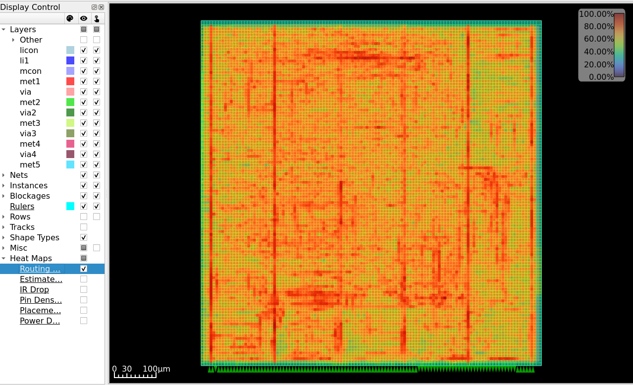
Fig. 21 Routing Congestion heat map — per-layer usage after Detailed Routing of aes_wb_wrapper.
Pin Density Map
Navigate to Heat Maps → Pin Density.
Pin density is a critical metric for cell placement health. An even distribution ensures the router can reach every input/output without detours that increase wire length and capacitance.
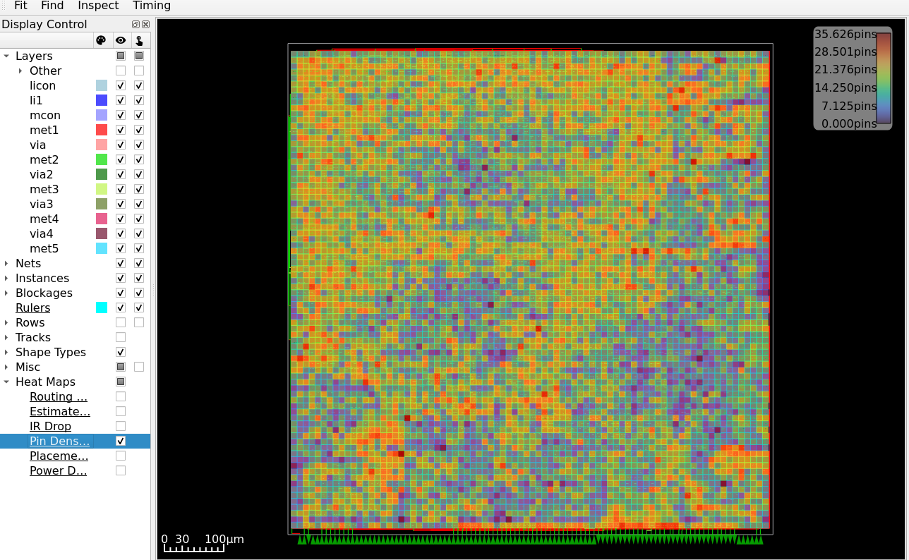
Fig. 22 Pin Density heat map — confirms even distribution of cell pins across the core.
7.2 Antenna Summary Report
To evaluate the effectiveness of the antenna repair process, antenna reports are analyzed at two stages: before and after the repair iterations.
📁 Report Locations
Pre-Repair (Initial Check)
runs/classic_flow/40-openroad-checkantennas/reports/antenna_summary.rptPost-Repair (Final Check)
runs/classic_flow/47-openroad-checkantennas-1/reports/antenna_summary.rpt
Initial Antenna Violations (Pre-Repair)
The following table illustrates the status after Global Routing but before the repair pass. Multiple nets, particularly in the AES core, show high violation factors on met3.
┏━━━━━━━┳━━━━━━━━━┳━━━━━━━━━━┳━━━━━━━━━━━━━━━━━━━━━━━━━━━━━━━━━━━━━━┳━━━━━━━━━━━━━━━━━━┳━━━━━━━┓
┃ P / R ┃ Partial ┃ Required ┃ Net                                  ┃ Pin              ┃ Layer ┃
┡━━━━━━━╇━━━━━━━━━╇━━━━━━━━━━╇━━━━━━━━━━━━━━━━━━━━━━━━━━━━━━━━━━━━━━╇━━━━━━━━━━━━━━━━━━╇━━━━━━━┩
│ 10.91 │ 4364.32 │ 400.00   │ _13723_                              │ _32156_/A        │ met3  │
│ 9.90  │ 3960.57 │ 400.00   │ aes.core.key[239\]                   │ _29805_/A1       │ met3  │
│ 8.37  │ 3347.81 │ 400.00   │ net1327                              │ _30458_/C        │ met3  │
│ 8.20  │ 3281.01 │ 400.00   │ _12804_                              │ _31204_/A        │ met3  │
│ 8.06  │ 3224.00 │ 400.00   │ _14664_                              │ _33146_/A        │ met3  │
│ 7.47  │ 2988.00 │ 400.00   │ aes.core.key[238\]                   │ _29807_/A1       │ met3  │
│ 7.27  │ 2909.14 │ 400.00   │ aes.core.key[236\]                   │ _29811_/A1       │ met3  │
│ 7.14  │ 2856.00 │ 400.00   │ net2783                              │ fanout2054/A     │ met3  │
│ 6.88  │ 2752.34 │ 400.00   │ net2819                              │ fanout2076/A     │ met3  │
│ 6.49  │ 2596.17 │ 400.00   │ aes.core.keymem.key_mem[1\][24\]     │ _31533_/B2       │ met3  │
│ 6.25  │ 2498.37 │ 400.00   │ _13579_                              │ _32005_/A        │ met3  │
│ 6.13  │ 2451.76 │ 400.00   │ _14816_                              │ _33306_/A        │ met3  │
Post-Repair Results
After the repair stage (utilizing diode insertion), the report is empty, confirming that all violations were successfully mitigated.
┏━━━━━━━┳━━━━━━━━━┳━━━━━━━━━━┳━━━━━┳━━━━━┳━━━━━━━┓
┃ P / R ┃ Partial ┃ Required ┃ Net ┃ Pin ┃ Layer ┃
┡━━━━━━━╇━━━━━━━━━╇━━━━━━━━━━╇━━━━━╇━━━━━╇━━━━━━━┩
└───────┴─────────┴──────────┴─────┴─────┴───────┘
Required
The maximum allowed Antenna Ratio defined by the PDK (e.g., Sky130).
This is the safety limit.P / R (Partial / Required)
The Violation Factor, used to determine whether a net is safe:Condition
Interpretation
P/R > 1.0
❌ Violation — repair required (diodes or layer hopping)
P/R < 1.0
✅ Safe — within allowed limits
Comparing the post-GRT and post-DRT antenna reports directly shows whether the repair pass eliminated all violations before Detailed Routing committed them to physical wires.
Note
It is normal for the post-DRT antenna report to contain a small number of residual violations. TritonRoute may introduce new short wire segments during the final DRC resolution pass that slightly exceed the repair margin. These are typically resolved during the Physical Signoff stage (Module 4) using Magic’s antenna checker.
- GRT
Global Routing. The first physical routing stage, which assigns nets to coarse routing regions (G-cells) to estimate congestion and RC parasitics without committing to actual wire shapes.
- DRT
Detailed Routing. The final routing stage, which transforms global routes into DRC-correct metal wires and vias using the TritonRoute engine.
- DRC
Design Rule Check. Verification that physical layout geometries conform to the foundry’s manufacturing constraints, including minimum spacing, width, and via enclosure rules.
- PDN
Power Distribution Network. The metal conductor grid delivering supply voltage (VDD) and ground (GND) to every standard cell in the design.
- STA
Static Timing Analysis. Timing verification performed by exhaustively checking all signal paths against declared constraints without requiring simulation vectors.
- WNS
Worst Negative Slack. The largest magnitude of negative slack across all failing timing paths.
- TNS
Total Negative Slack. The arithmetic sum of all negative slack values across every failing timing path.
- PnR
Place and Route. The physical design stage encompassing standard cell placement and signal wire routing.
- SDC
Synopsys Design Constraints. A Tcl-based format specifying timing and clocking constraints for implementation and static timing analysis.